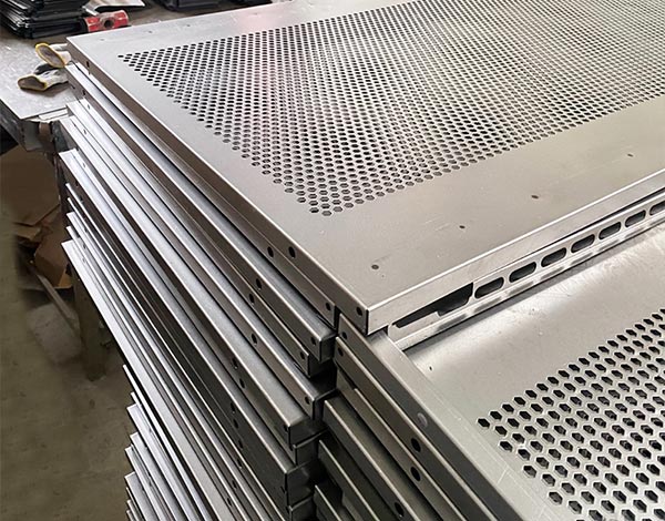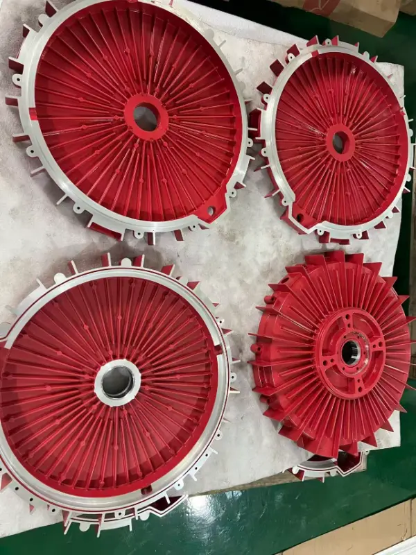
Selecting a metal casting route involves more than identifying a metal and creating a mold. Part geometry, wall transitions, internal cavities, dimensional requirements, production volume, machining allowance, and service conditions all influence the result. This guide explains how common processes differ, what to include in a technical drawing, how to anticipate quality risks, and when secondary machining or surface treatment is necessary. It is intended to help engineering, sourcing, and manufacturing teams assess a component as a complete production task rather than as a shape alone.
Select a section to jump to the details
Casting forms a component by directing molten metal into a mold cavity and allowing it to solidify. The cavity reproduces the intended shape, while the selected alloy and solidification conditions influence the component's structure and properties. Depending on the route, the mold may be made from expendable sand, a ceramic shell, or a reusable metal die.
For a custom component, engineering begins before metal is poured. The drawing must describe the shape and the features that matter in service. The manufacturing team then considers mold construction, metal flow, feeding during solidification, removal from the mold, and any operations needed after casting.
Review geometry, functional surfaces, alloy requirements, assembly interfaces, and inspection criteria.
Choose the process, design the mold system, and plan how the molten metal fills and feeds the cavity.
Remove gates and excess material, carry out specified machining or treatments, then inspect critical features.
The stages connect to one another. A hole that will be drilled after casting needs a clear datum and sufficient machining allowance. A sealing surface may require a tighter finish than a nonfunctional outer face. An internal passage can affect both mold design and inspection access. Addressing these points early helps prevent a design that is easy to draw but difficult to manufacture consistently.
Different processes accommodate different combinations of size, shape, surface detail, alloy, repeatability, and tooling approach. No single route is ideal for every component. The best comparison starts with the part's functional needs and then checks whether each process can form the required geometry and meet the drawing requirements.
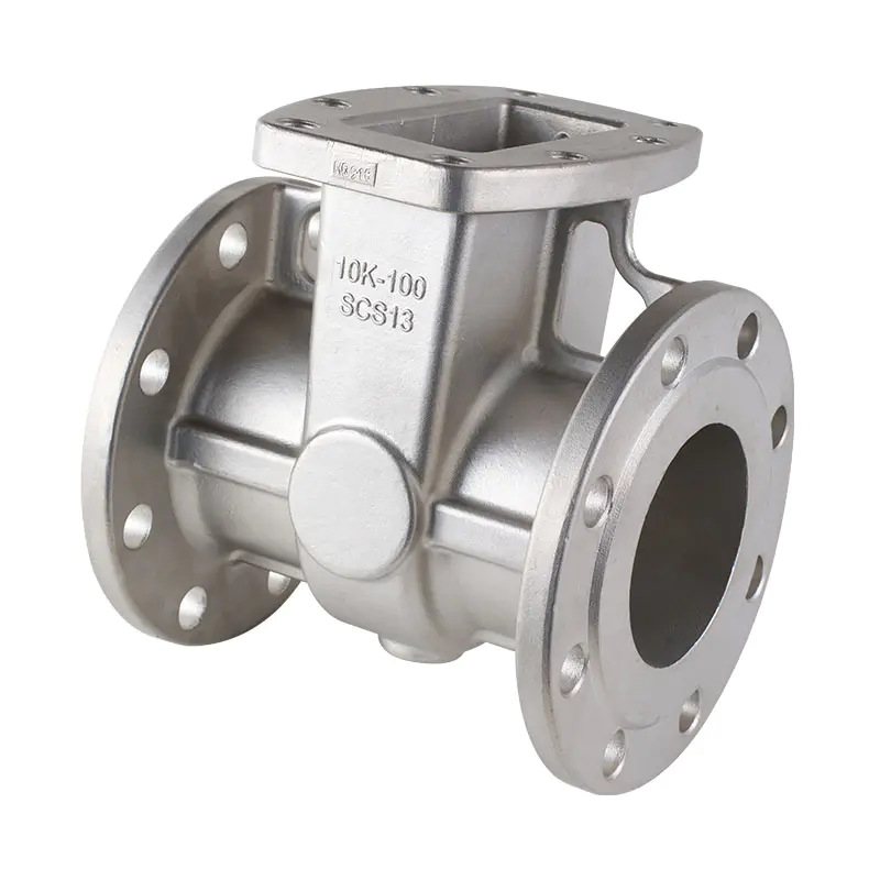
Sand casting uses a sand-based mold, which is generally broken apart to release the solidified part. It can suit large housings, machine bases, pump components, valve bodies, and geometries that would be difficult to remove from a permanent die. Cores can form internal cavities or passages. The achievable surface condition and dimensional consistency depend on the mold system, alloy, part size, and process controls, so critical interfaces may need machining.
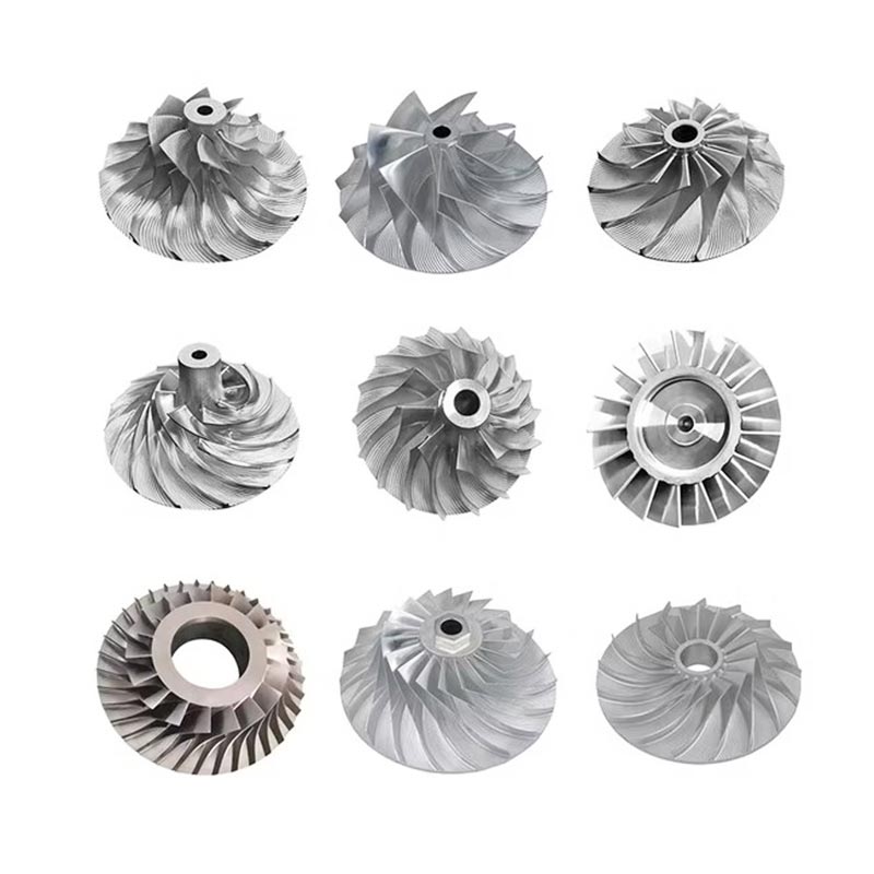
Investment casting typically forms a ceramic shell around a pattern that is removed before pouring. It is useful for detailed shapes, curved passages, and components where several features need to be integrated into a single geometry. The route can reduce the amount of material that must be removed from some shapes, but the design still needs to account for alloy behavior, section changes, finishing needs, and the tolerances required on functional features.
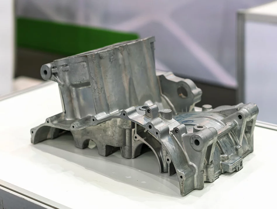
Die casting forces molten metal into a reusable metal die. It is commonly considered for aluminum, zinc, and selected other nonferrous alloys where the component geometry and planned production pattern suit the tooling. The process can produce detailed shapes at a repeatable pace, but die access, draft, parting lines, ejection, and wall uniformity require early attention. Alloy and machine selection also limit which process variants are appropriate.
| Process | Often considered for | Design points to review |
|---|---|---|
| Sand casting | Large parts, housings, complex cavities, a range of ferrous and nonferrous alloys | Core placement, mold access, section transitions, machining allowance, surface requirements |
| Investment casting | Detailed geometry, relatively intricate features, shaped components with limited access for machining | Shell and pattern constraints, local thickness, alloy suitability, critical dimensions, finishing |
| Die casting | Repeatable nonferrous parts with geometry suited to a reusable die | Draft, parting line, ejection, wall consistency, die access, production requirements |
A comparison should also include the operations that follow the mold stage. A part that needs multiple precision bores, threaded holes, or flat sealing faces may require extensive machining regardless of how well the initial shape is formed. For these components, evaluate the casting route and machining plan together rather than treating them as separate decisions.
Material selection should start with the environment in which the component will operate. Loads, temperature, corrosion exposure, wear, fluid contact, weight limits, and joining requirements can point toward different alloy families. The choice also affects melting behavior, mold compatibility, solidification, machinability, and the finishing operations available.
For a metal casting project, a material name alone is not a complete specification. A drawing or technical brief should identify the required grade where known and describe any relevant performance criteria. If several grades are technically possible, compare them against the component's operating conditions instead of selecting only by a broad label such as steel or aluminum.
| Material family | General characteristics | Questions to settle during selection |
|---|---|---|
| Aluminum alloys | Often selected where lower component mass and useful thermal conductivity are important | Which grade is required? What loads, temperatures, corrosion exposure, and machining features apply? |
| Stainless steel | Used where corrosion resistance and mechanical performance are important, depending on grade and environment | What media will contact the part? Is the selected grade suitable for the operating environment and joining method? |
| Carbon steel | Available in grades used for a broad range of structural and industrial component requirements | What strength or toughness is needed? Is heat treatment or protective finishing specified? |
| Alloy steel | Alloying elements and heat treatment can support specific strength, hardenability, or wear requirements | Which grade and condition are required? What inspection and post-casting treatment are necessary? |
An alloy's properties do not by themselves guarantee a finished component will meet every requirement. The casting route, part geometry, local solidification behavior, heat treatment, machining, and inspection all affect the final outcome. When the part has safety-related or pressure-containing duties, specify the applicable material condition and the acceptance criteria instead of relying on a generic alloy description.
Where the specification is not yet fixed, give the manufacturer enough context to discuss suitable options: operating temperature, type of load, exposure to fluids or chemicals, expected wear, and interfaces with neighboring parts. A technical discussion can then focus on practical trade-offs without losing sight of the component's main purpose.
Design for manufacturability connects the CAD model to the way the mold is made, filled, opened, and inspected. A visually compact design may create heavy sections, inaccessible cavities, or abrupt transitions that complicate solidification. Reviewing these features before tooling is committed gives the team an opportunity to revise geometry while changes remain practical.
Large differences in section thickness can cause areas to cool at different rates. Heavy junctions may remain hot longer than adjacent walls, creating conditions that encourage shrinkage-related defects. Where the design permits, maintain reasonably consistent wall thickness, blend transitions, and consider coring out unnecessary solid masses. The appropriate geometry depends on the process, alloy, and component dimensions, so generic numerical rules should not replace a drawing-specific review.
Rounded transitions can improve metal flow and reduce abrupt changes in section. They may also reduce stress concentrations in service, depending on the load path. A radius should be selected with functional clearances and machining access in mind; it must not interfere with mating components or create an unwanted thick region where walls meet.
Draft is a slight taper that helps a pattern or casting release from the mold or die. The amount needed depends on the process, surface depth, texture, material, and tooling arrangement. Permanent dies also require a workable opening direction, ejection strategy, and parting-line location. Internal passages may need cores, and each core adds design and manufacturing considerations. Identify which surfaces must remain free of parting marks or ejection evidence so those requirements can be considered during tooling design.
Not every surface needs the same dimensional control. Mark the bores, mounting faces, sealing lands, threaded features, and interfaces that determine fit or function. Machining allowance should be sufficient for the intended operation while avoiding an unnecessarily thick removal layer that could expose subsurface discontinuities. The drawing should identify datums and geometric relationships so inspection can assess the part in the same way it is assembled or used.
These checks are central to metal casting design because geometry affects more than the appearance of the as-cast part. It also influences how reliably the mold fills, how the component solidifies, whether it can be removed without damage, and how easily critical dimensions can be completed later.
Quality planning for a metal casting component should be tied to its function and the defects that could affect it. A general visual check can reveal surface irregularities, but it cannot prove the absence of internal discontinuities. Likewise, a dimensional inspection confirms measured geometry, not every aspect of material integrity. Inspection methods should be chosen to answer defined acceptance questions.
| Condition | What it may indicate | Why the part design matters |
|---|---|---|
| Porosity | Gas-related voids or cavities associated with filling, mold conditions, or solidification | Can be important near pressure boundaries, thin walls, machined faces, or highly loaded sections |
| Shrinkage | Voids or unsound areas where metal contraction was not adequately fed during solidification | Thick junctions and isolated hot regions may require attention in the geometry and feeding plan |
| Misrun or cold shut | Incomplete filling or an inadequate meeting of metal fronts | Long thin paths, narrow features, and complex flow paths can be more challenging to fill |
| Inclusions | Unwanted nonmetallic or other foreign material within the casting | Acceptance depends on location, size, specification, and the component's service requirements |
| Distortion | Shape changes during cooling, release, handling, or subsequent treatment | Long spans, asymmetry, and uneven section distribution can affect dimensional stability |
Visual examination can identify surface discontinuities, flash, damage, and obvious finishing issues. Dimensional measurement checks defined sizes and geometric relationships against the drawing. Depending on the material, geometry, and acceptance plan, other methods such as radiographic, ultrasonic, or penetrant testing may be considered. No single method answers every question; test selection should account for defect type, location, access, material, and the required level of confidence.
For components with pressure, structural, or safety-related duties, confirm the applicable standard, inspection extent, and acceptance criteria before production begins. State whether the requirement applies to the raw casting, after heat treatment, after machining, or to the completed part. This avoids ambiguity when the same feature is evaluated at different manufacturing stages.
The as-cast shape is often a starting point rather than the final condition. Casting can form external contours and internal features, while machining brings selected surfaces or holes to the dimensions needed for assembly and operation. The right sequence depends on which surfaces must be accurate, how the part will be located during machining, and whether heat treatment or finishing may alter its dimensions.
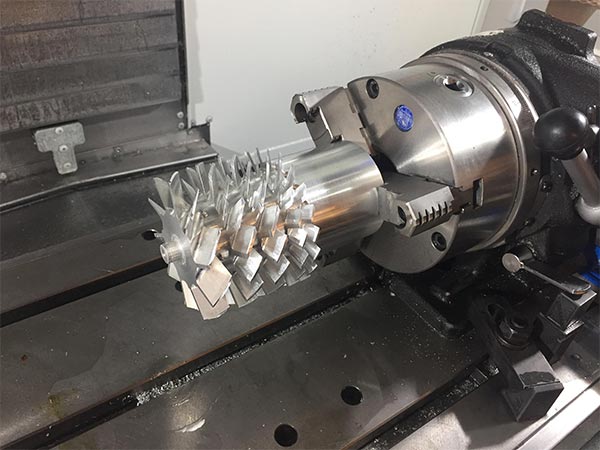
CNC milling, turning, drilling, boring, and tapping can be used where the drawing requires specified dimensions, flatness, position, threads, or surface finish. The casting design should leave enough stock for those operations and provide datums that can be located repeatably. Avoid assuming every surface should be machined: unnecessary machining may add setup complexity and may remove material from areas that only need an as-cast finish.
Some alloys or applications require heat treatment to achieve a specified material condition. The appropriate cycle depends on the grade, section size, property targets, and applicable technical requirements. Treatment can also affect distortion and final dimensions, so critical machining stages and inspection points should be sequenced accordingly.
Surface treatment can be used to address corrosion exposure, appearance, wear, cleanliness, or other functional needs. The correct method depends on the base alloy and the service environment. Specify the required finish and the areas to be treated, including any surfaces that must be masked or protected. Where a coating changes a fitted dimension, that effect should be included in the tolerance plan.
Integrated production planning is especially useful when a component needs a combination of casting, machining, heat treatment, finishing, and dimensional inspection. A coordinated plan clarifies when each requirement applies and reduces the risk of discovering a conflict after one operation has already been completed.
A complete brief helps a manufacturer evaluate the component rather than guess at the intended use. A 3D model shows the shape, but it may not identify every critical dimension, material condition, inspection rule, or finishing requirement. A drawing and supporting notes should explain the features that must be controlled and distinguish essential requirements from details that do not affect performance.
When requesting a manufacturing review for metal casting, organize the information into a compact technical package:
Before a route is finalized, align on parting-line acceptability, draft, core requirements, machining stock, inspection access, and the dimensions that determine assembly. If the drawing contains a tolerance that is tighter than the function requires, the design team can assess whether it can be relaxed. Conversely, if a feature is essential to sealing or alignment, its importance needs to be visible on the drawing and in the inspection plan.
Change control also matters. When a drawing revision changes a wall, hole, datum, or material, the effect may extend beyond that individual feature to tooling, machining fixtures, and inspection methods. Keeping file versions and approval status clear helps ensure the manufacturing plan follows the intended design.
Application is a useful starting point because it explains why the geometry and material matter. Two parts with similar outer dimensions may need different production routes when one holds fluid pressure and the other acts as a noncritical cover. Function should guide the priorities for material, wall sections, machining, testing, and finishing.
Housings, valve bodies, bonnets, and fittings may include cavities, ports, flange faces, and threaded connections. Define pressure-related requirements, sealing surfaces, wall regions that must remain sound after machining, and the inspection needed for the intended service. A casting route should be considered alongside the machining plan because the final ports and sealing interfaces may be produced in secondary operations.
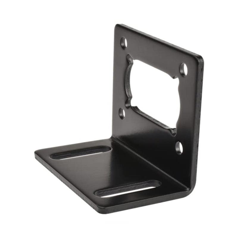
Machine frames, brackets, supports, and actuator components can prioritize stiffness, alignment, mounting relationships, vibration behavior, or weight. The drawing should clearly identify mounting datums and interfaces with other components. For parts with long spans or asymmetrical geometry, discuss distortion and how the component will be held during machining and measurement.
These applications span a wide variety of operating conditions. Some components are primarily structural; others experience heat, cyclic loading, corrosion, or demanding sealing requirements. The correct process cannot be selected from the industry label alone. It should follow the specific alloy, geometry, inspection needs, production context, and functional acceptance criteria.
Across applications, the strongest starting point is a clear description of what the component must do and which features determine success. That information makes it possible to evaluate process limitations, identify design changes worth discussing, and coordinate the raw casting with all downstream operations.
These answers cover common engineering and sourcing questions that arise while planning a custom cast component.
No. Processes differ in the size and geometry they can accommodate, the alloys available, the surface condition produced, tooling requirements, and dimensional capability. Compare candidate routes against the component's functional features and the planned downstream operations.
Machining may be needed for accurate bores, threads, flat faces, sealing surfaces, fits, or positional relationships that the selected casting route cannot provide directly to the drawing requirement. Only the necessary areas should be specified for machining.
In many cases, cores or process-specific tooling can form internal cavities and passages. Feasibility depends on passage shape, wall thickness, access, core stability, cleaning needs, and how the finished feature can be inspected. The passage should be reviewed during the design stage.
A current 2D drawing, a matching 3D model, the specified alloy or operating requirements, critical tolerances, intended application, finishing needs, and inspection criteria provide a useful starting package. Production context and revision status help clarify the manufacturing plan.
Identify the feature or condition to be checked, the applicable method or standard where specified, the manufacturing stage, and the acceptance criterion. Visual checks, dimensional measurement, and internal examination answer different questions and should not be treated as interchangeable.
Machining, heat treatment, and surface finishing can affect dimensions, surface condition, sequence, and inspection access. Planning them with the initial casting route helps avoid conflicts such as insufficient machining allowance or a coating that interferes with a fitted surface.
Share the drawing, material requirements, critical dimensions, operating conditions, and any machining or finishing needs. A project review can then focus on process suitability, manufacturability, and the checks required for the finished component.
Explore the capabilities of BestPro and contact us to discuss your custom component.
Final process selection should be based on the component drawing, material specification, service conditions, and agreed acceptance criteria.
-